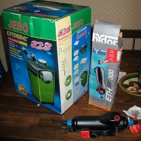
Filter Construction
The motor assembly is held on the body by two large side clips. The clips have a robust feel and a satisfying snap when closed. This forces the indented top edge of the media housing against a recessed o-ring in the motor assembly. The assembly feels solid when closed. Inside are 4 baskets with included media. The power head itself has the obligatory inlet and outlet, and these are angled slightly and fixed- they don't move. The filter comes with shutoff fittings that are screwed into the inlet and outlet. They are differentiated by different size output tubes, and you have to pay attention during the installation as the disconnects can be reversed. The motor assembly has "IN" and "OUT" helpfully molded on the top. Don’t expect to be able to read that in the darkness of an undertank cabinet- they’re too hard to see for that, but they are there. Hose attachment to the shutoff is via a castellated compression fitting and collar nut. Insert hose, tighten collar, and voila. The shutoffs cut the flow via two individual stopcock handles- one in each disconnect.
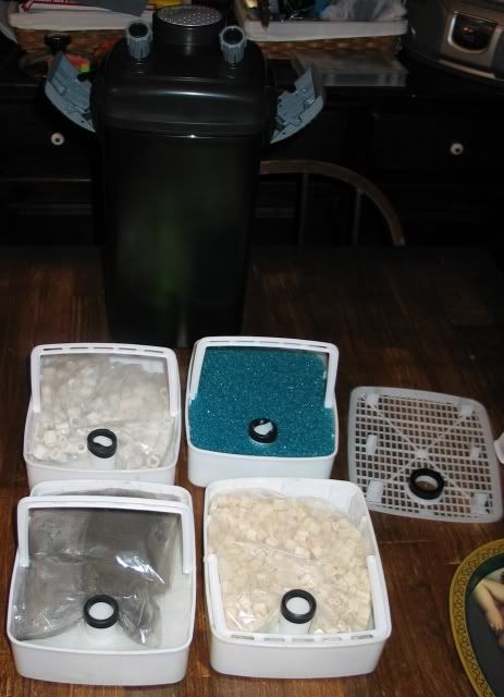
The filter body comes with 4 baskets complete with media. At the top is a grate, and under that the topmost basket has 2 sponges, 1 each of coarse and fine, the second basket has small porous ceramic media, the 3rd larger ceramic media, and the bottom has activated carbon. The 2, 3 & 4 baskets have some sort of woven material in the bottom as well, that serves to keep media from falling through the baskets. Water comes in and travels top-to-bottom through the canister. The volume of media in this very large filter is quite impressive- enough to maintain a biological filter far beyond the needs of a planted tank. A tube is built into each of the baskets and the top grate, with the top of each tube fitted with a rubber gasket. The gasket fits into the bottom of the tube in the basket above it, so that one long tube is created from the bottom to the top when they're all nested together properly. The gasket in the grate then fits into the impeller chamber in the motor assembly, so that water is drawn up from the bottom of the canister. The close-fitting baskets and design of the grate is such that it looks highly improbable bypass will occur in this design. Water flows through the media from top to bottom, returning through the segmented/gasketed tube. Fitting all the parts together and getting the gaskets and tubes to seat properly was a bit fiddly, especially when trying to place each of these into the close-fitting housing. At this point, you find out why each of the baskets is equipped with its own handle. Removal or replacement would be pretty difficult without them. I found if things aren't placed just right with all the gaskets properly seated, the housing clips can't both be properly secured.
There is a large round priming button on the top of the motor housing that prevents the need for awkward priming. Just push the plunger down and it evacuates air from inside the filter through the return hose and draws water in through the intake. This is a real plus.
Documentation
The filter comes with an instruction manual, and it wasn't written by a native speaker of English, and could present some difficulty to the not-so-mechanically-inclined. Some important discrepancies caused me to wonder. In one part, the directions claim the outlet spouts can be positioned, yet in my unit they cannot. The directions are inconsistent. A part is referred to by one name in the illustrated parts list, and by several other names in the directions. Included assembly illustrations use yet other names for parts. Relying on these instructions makes the assembly process somewhat confusing. The tube of "sealant" is never mentioned anywhere in the entire pamphlet. My guess is, it's o-ring lube. I didn't open it, as everything went together without the need of undue persuasion and I didn’t get any leaks. The first time I do maintenance, though, I hope things come apart as easily as they went together!


")