I'm currently in the early stages of a new tank project. The new aquarium is 130 gallons with canister filtration, and I want to have inline heat. Unfortunately, the inline heaters I have used in the past (Ista brand) have a new design that utilizes a staged 1/2"-5/8" barb that would be overly constrictive for a tank this size. I considered splitting the return line with a Y barb and doubling up on the heaters, but I thought I could maybe rig something up with some PVC and a standard probe/controller that would be more substantial and that could support whatever size plumbing I want.
I have seen DIY inline heaters that nest the body of the heater probe itself in a cable gland. I'm sure this works fine, but I really would prefer to have the entirety of the probe in the water, and I also want to be able to use a temperature controller like an Inkbird. So, I'm going in a slightly different direction here.
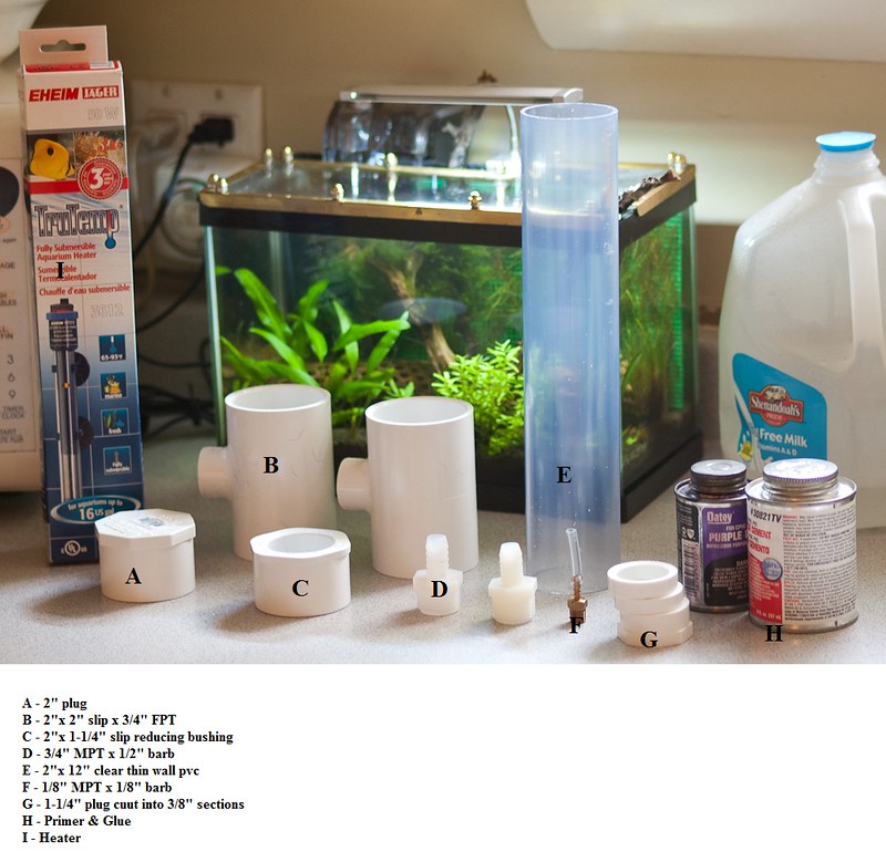
The basic design uses 2" fittings (a wye, a tee, and a union) with cable glands for the heater cord and the controller thermometer probe.

Since the entire heater (500w) is going inside the PVC housing, I need to cut and re-splice the cord to be able to get it through the cable gland. I'm using wire nuts for the splice, but I will be enclosing the spliced portion of the cable in its own PVC housing (a 2" slip coupler with 2"x1/2" reducers and cable glands on the ends).
The end of the housing where the heater cord exits has a union (to make future changeouts of the heater probe simple). The cut heater cord is nested in a cable gland threaded into one side of the union:

The controller's temperature probe is nested in a gland inserted into the tee:

Once the heater cord was nested in the gland, I spliced it back together and enclosed it within its own waterproof housing. In addition to making it water proof, the cable glands at the ends of the housing will also prevent the wires from torquing which will immobilize the spliced portion of the power cord. From what I can tell, this is the same thing that Aqua Ultraviolet does with the power cords on their UV sterilizers.


I've currently got it hooked up to a spare canister and the utility sink in the laundry room:

So far so good!
One of the features that was important to me for this project was that the heater should shut itself off if the pump stopped circulating water. A temperature controller is no good for this if the temperature probe is in the tank - hence the placement in the body of the inline heater itself. To test, I shut off the canister and left the controller/heater on. It took about a minute for the temperature inside the housing to go from 72 to 78 and cut off power to the heater. After the controller shut off, the temperature in the housing continued to rise until leveling off at 85 degrees.
All in all, I'm pleased with how this came together, though I do want to trade out this old Hygger controller for a spare Inkbird I have laying around. With this controller, the probe itself is nested in the gland, and only about 2/3 of the probe is in the water. I think this is affecting the reliability of the temperature readings. Unfortunately the cord on the Inkbird's temperature probe is too small for the glands I have, but I have a plan to make it work. I'll follow up here when that's complete and tested.
Thanks for reading!
I have seen DIY inline heaters that nest the body of the heater probe itself in a cable gland. I'm sure this works fine, but I really would prefer to have the entirety of the probe in the water, and I also want to be able to use a temperature controller like an Inkbird. So, I'm going in a slightly different direction here.
The basic design uses 2" fittings (a wye, a tee, and a union) with cable glands for the heater cord and the controller thermometer probe.
Since the entire heater (500w) is going inside the PVC housing, I need to cut and re-splice the cord to be able to get it through the cable gland. I'm using wire nuts for the splice, but I will be enclosing the spliced portion of the cable in its own PVC housing (a 2" slip coupler with 2"x1/2" reducers and cable glands on the ends).
The end of the housing where the heater cord exits has a union (to make future changeouts of the heater probe simple). The cut heater cord is nested in a cable gland threaded into one side of the union:
The controller's temperature probe is nested in a gland inserted into the tee:
Once the heater cord was nested in the gland, I spliced it back together and enclosed it within its own waterproof housing. In addition to making it water proof, the cable glands at the ends of the housing will also prevent the wires from torquing which will immobilize the spliced portion of the power cord. From what I can tell, this is the same thing that Aqua Ultraviolet does with the power cords on their UV sterilizers.
I've currently got it hooked up to a spare canister and the utility sink in the laundry room:
So far so good!
One of the features that was important to me for this project was that the heater should shut itself off if the pump stopped circulating water. A temperature controller is no good for this if the temperature probe is in the tank - hence the placement in the body of the inline heater itself. To test, I shut off the canister and left the controller/heater on. It took about a minute for the temperature inside the housing to go from 72 to 78 and cut off power to the heater. After the controller shut off, the temperature in the housing continued to rise until leveling off at 85 degrees.
All in all, I'm pleased with how this came together, though I do want to trade out this old Hygger controller for a spare Inkbird I have laying around. With this controller, the probe itself is nested in the gland, and only about 2/3 of the probe is in the water. I think this is affecting the reliability of the temperature readings. Unfortunately the cord on the Inkbird's temperature probe is too small for the glands I have, but I have a plan to make it work. I'll follow up here when that's complete and tested.
Thanks for reading!